

AntiSnapback modules address one of the most critical GCC issues for competitive play - snapback! Snapback is physical overshoot that occurs as the joystick rapidly returns to center, and can cause unintended behaviors such as accidental turnarounds, jumps, etc. Snapback modules address this by acting as electrical low-pass filters and eliminating unintentional inputs. Each module can be fine-tuned to match the its controller, and the no-reset feature means the module won’t cause drifting or require a reset!
Time:
15-30 min
Difficulty:
Type:
Performance / Functional Mod
Tools Required:
- Screwdrivers Triwing Y2.5 for stock screws.
Torx T8 if you’ve done the torx screw upgrade
Torx T5 if you have a FIRES rumble bracket - Soldering equipment
- Wire strippers (28 gauge)Recommended: Klein Tools 11057 Wire Stripper
- Tweezers or fine needle-nosed pliers
- 90%+ isopropyl alcohol
- Extra VHB tape (Optional) If you need to remove and reattach a module - or replace the adhesive for any other reason - use 3M 5952 VHB tape.
- Flush cutters (w/ OEM rumble bracket) Recommended: Hakko CHP-170 Micro Cutter
Parts List:
- FIRES No-Reset AntiSnapback Module: Available on FIRES Etsy store
Installation:
Open controller shell and take out PCB:
Remove the six shell screws. Set aside the bottom half of the controller and remove the circuit board from the top half. You can also set aside the top shell.
Module placement:
Before placing the module, clean that spot on the PCB with 90%+ isopropyl alcohol. This will remove any residual oils and/or soldering flux that could cause the mounting adhesive to release over time.
The AntiSnapback module comes mounted to a 3D-printed bracket with (extremely strong) VHB 5952 double-sided adhesive on the bottom. Peel off the red liner and adhere the module at the location shown - the bottom-right of the PCB’s rear side. The base of the module should roughly line up with the bottom and right edges of the PCB.
Remove rumble bracket:
Remove the rumble motor from the bracket and lay it to the side. Then:
For OEM rumble brackets, undo the plastic clips above the trigger potentiometers and pull the bracket off.
For FIRES rumble brackets, unscrew the two retaining screws, slide the bracket forwards (towards the cable), then lift the bracket off.
Plug in wire assembly, trim, & strip:
With the module in place and rumble bracket removed, plug in the included wire set (it will only fit one way).
Next, cut the wires to length, but be very careful not to cut them too short… the wires shown in this photo are too short! The wires will run along the PCB and will end up longer than you might initially think. Err on the side of making them too long - you can always cut them shorter later.
The bottom wire runs to the vertical potentiometer andn thus will be much longer than the others.
Strip the end of each wire (these wires are 28 gauge).
Solder wires:
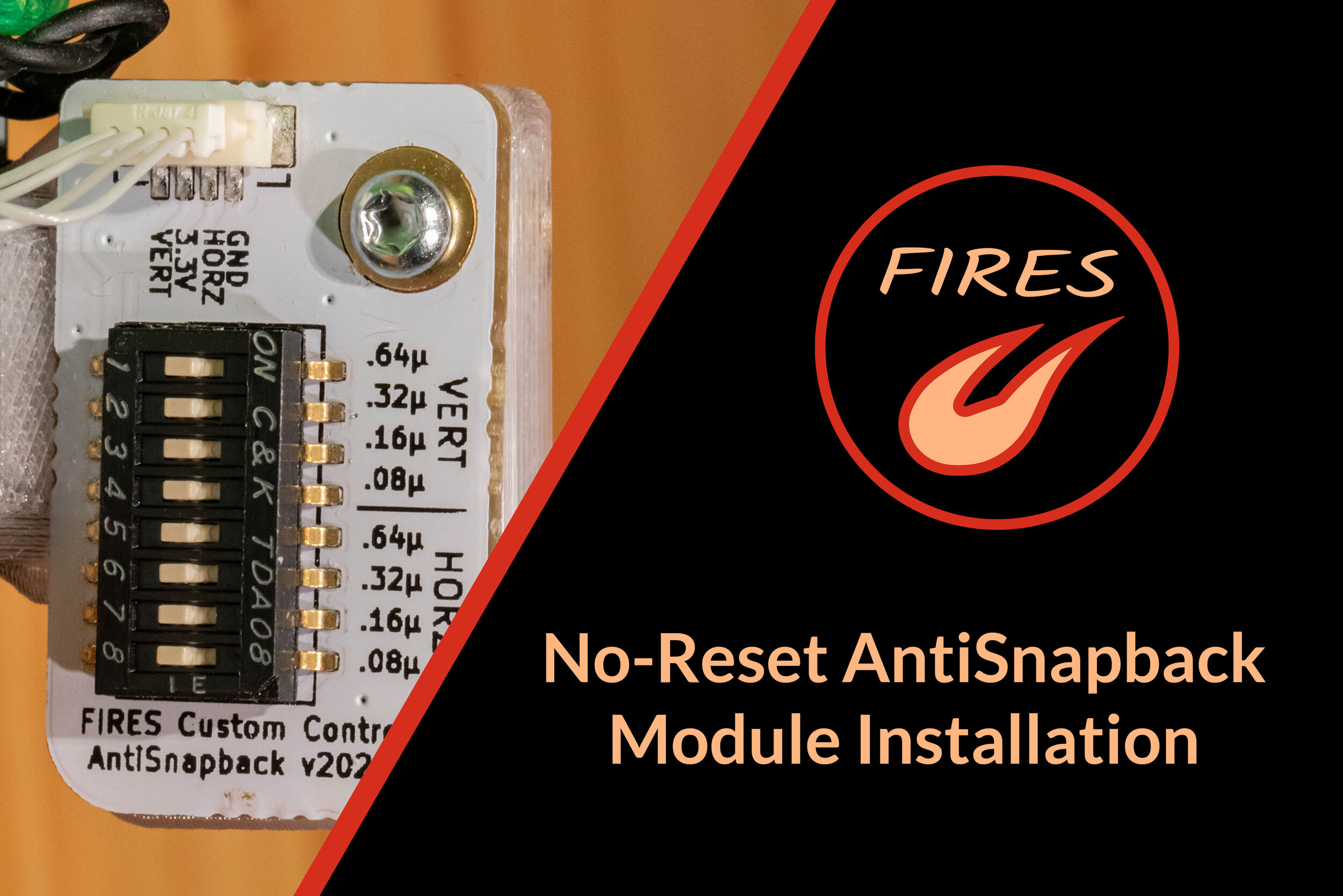
Solder each wire to its respective potentiometer lead as shown. Due to the small size of the wires, tweezers are extremely helpful here! From top-to-bottom, the order of wires on the module is:
GND
HORZ
3.3V
VERT
It’s helpful to apply flux beforehand so the solder melts and solidifies nicely! If you don’t have much experience soldering, be sure to check out the soldering guide (and do some practice first).
Modify rumble bracket (OEM rumble bracket only):
The OEM rumble bracket has a solid rear sidewall. It needs to be modified so the snapback module wires may pass through it. If you are using an OEM bracket, use small flush cutters to trim a passage for the wires - try not to trim away any more than you need to!
The FIRES rumble bracket is designed with this passage already and needs no modification.
Reinstall rumble bracket, check fit, peel sticker:
With the module installed, you can re-install the rumble bracket and double check that everything fits. Make sure the digital trigger wires run behind the bracket (not above it!)
The module switches may be covered by an amber sticker - if so, feel free to peel that away now!
AntiSnapback Module Tuning:
Measuring snapback:
The best way to measure / test for snapback - and tune modules - is using SmashScope. Enter the Oscilloscope Mode and use the Main Stick Snapback testing screen. Flick the stick to one side and observe the snapback waveform (also note the green threshold values of +23 / -23). Your goal is not to eliminate snapback entirely, just to reduce the overshoot so it consistently stays below the green threshold value of +/-23. Trying to eliminate all overshoot will require substantially more capacitance… this will cause your faster inputs to be filtered out.
Another quick-and-dirty way of testing uses the Smash Melee character select screen (“CSS”). With the cursor all the way to one side of the screen, flick the analog stick towards that side and observe whether snapback causes the cursor to slightly move back from the edge. If it does, you have snapback!
Regardless of which tool you use, always do several trials since there will always be some variance.
More text information is below, however I highly recommend checking out this video guide on snapback module tuning. All credit to Solanum Customs!
Tuning capacitor module:
The goal of module tuning is to add just enough capacitance to eliminate problematic snapback, but no more. Excessive capacitance is undesirable as your faster inputs will start to be filtered out. This is why we seek a “goldilocks” value where snapback is eliminated, but your intentional inputs aren’t affected.
Each axis has four capacitance values (0.08, 0.16, 0.32, and 0.64 microfarads) which can each be individually turned “on” and “off”. These values add to each other, resulting in 16 different possible combinations per axis.
Each switch is “off” when down and “on” when up. Use a small tool (such as tweezers or toothpick) to flip switches up and down.
Using one of the methods above, slowly add more capacitance until you have successfully mitigated snapback. Each axis should be tuned independently. Also, be sure to check both directions on each axis (they sometimes behave differently!)
A good starting point for capacitor tuning is the 0.32u setting - typically GCCs need around this value or greater.
Reassemble Controller:
With the module installed and tuned, you’re all set to reassemble! You may find that the module needs adjustment over time - this is normal. Just open it back up and follow the process above!
