
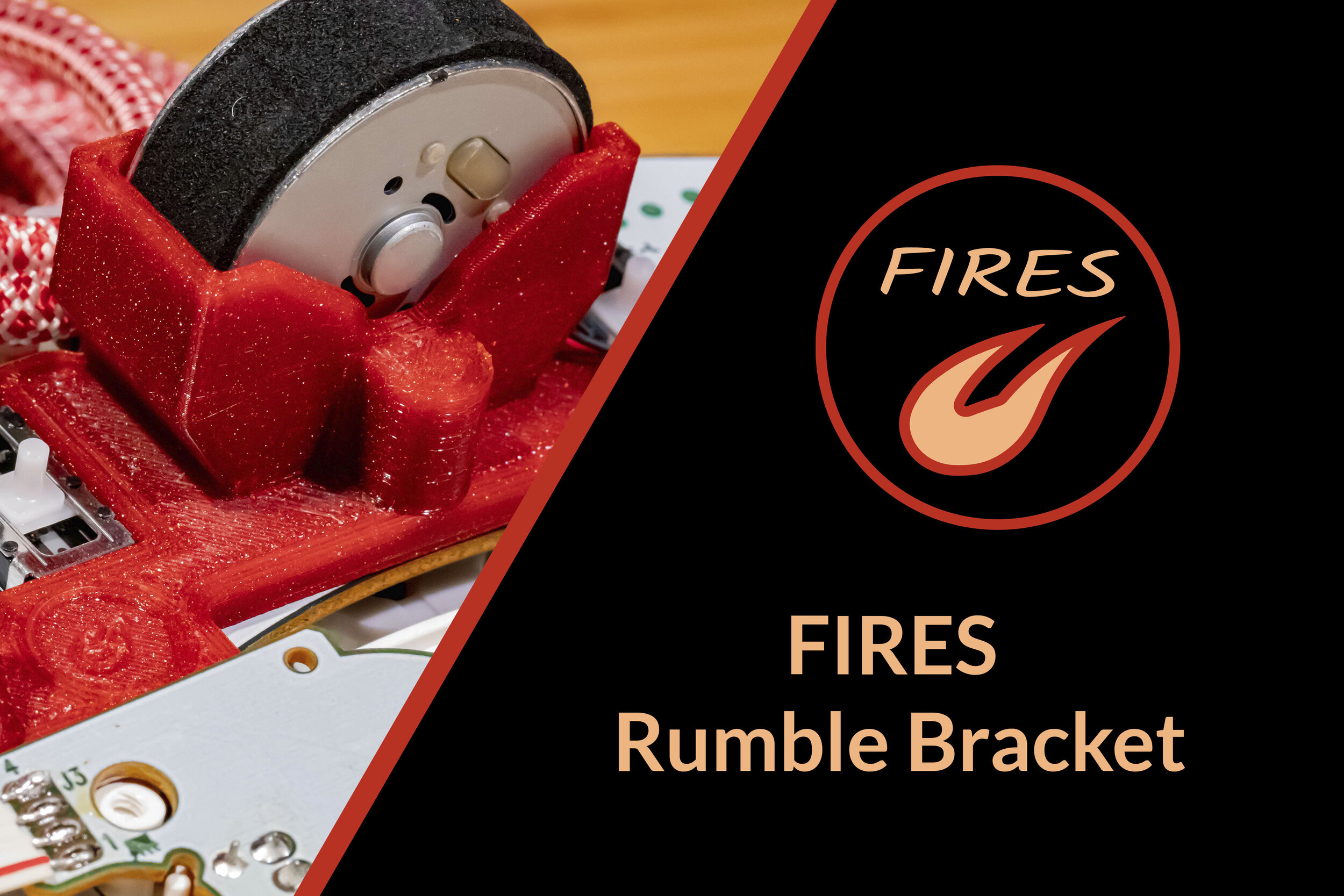

Custom rumble brackets for better aesthetics and quality-of-life improvements! This design offers numerous improvements:
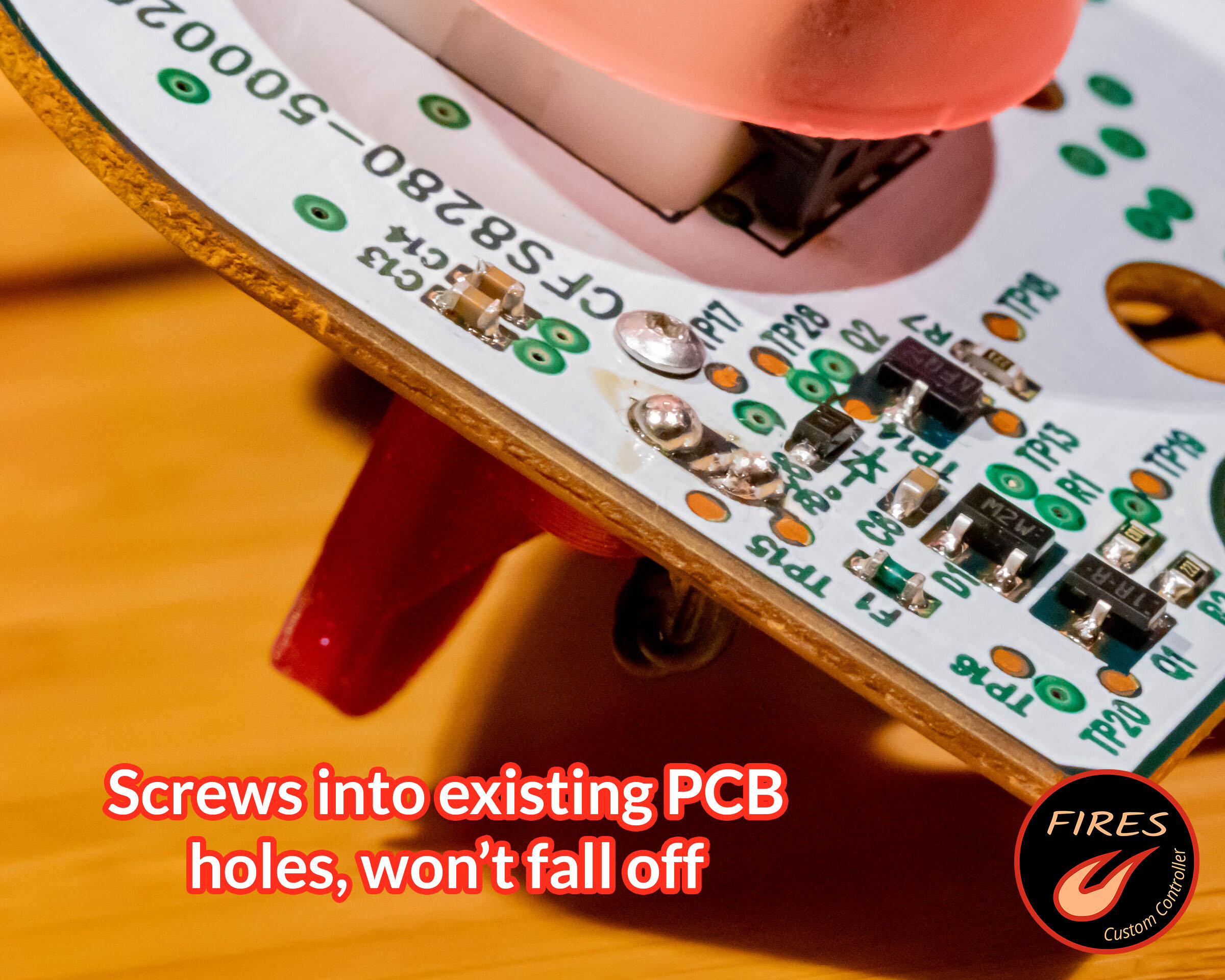
Screw-down design won't fall off the circuit board
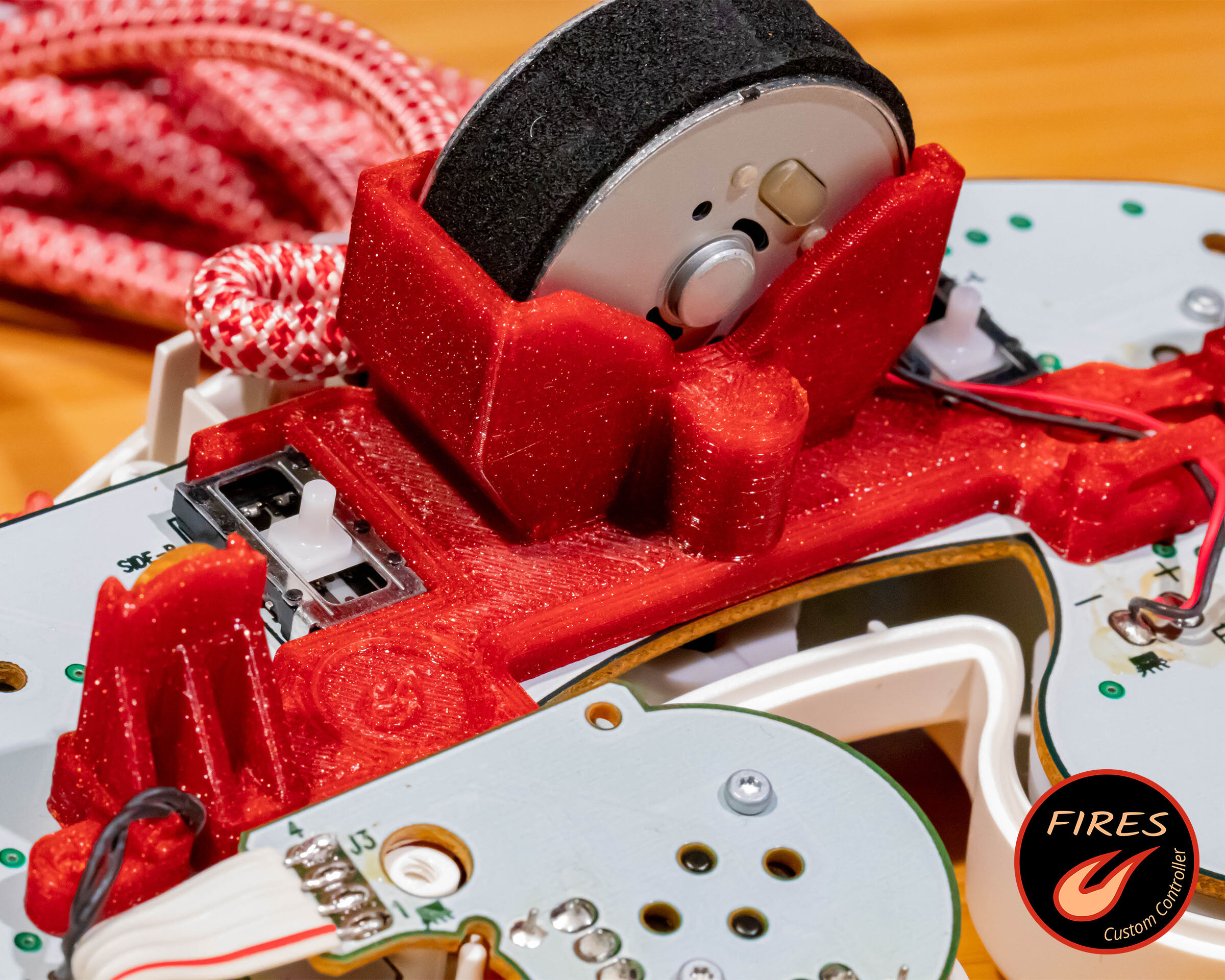
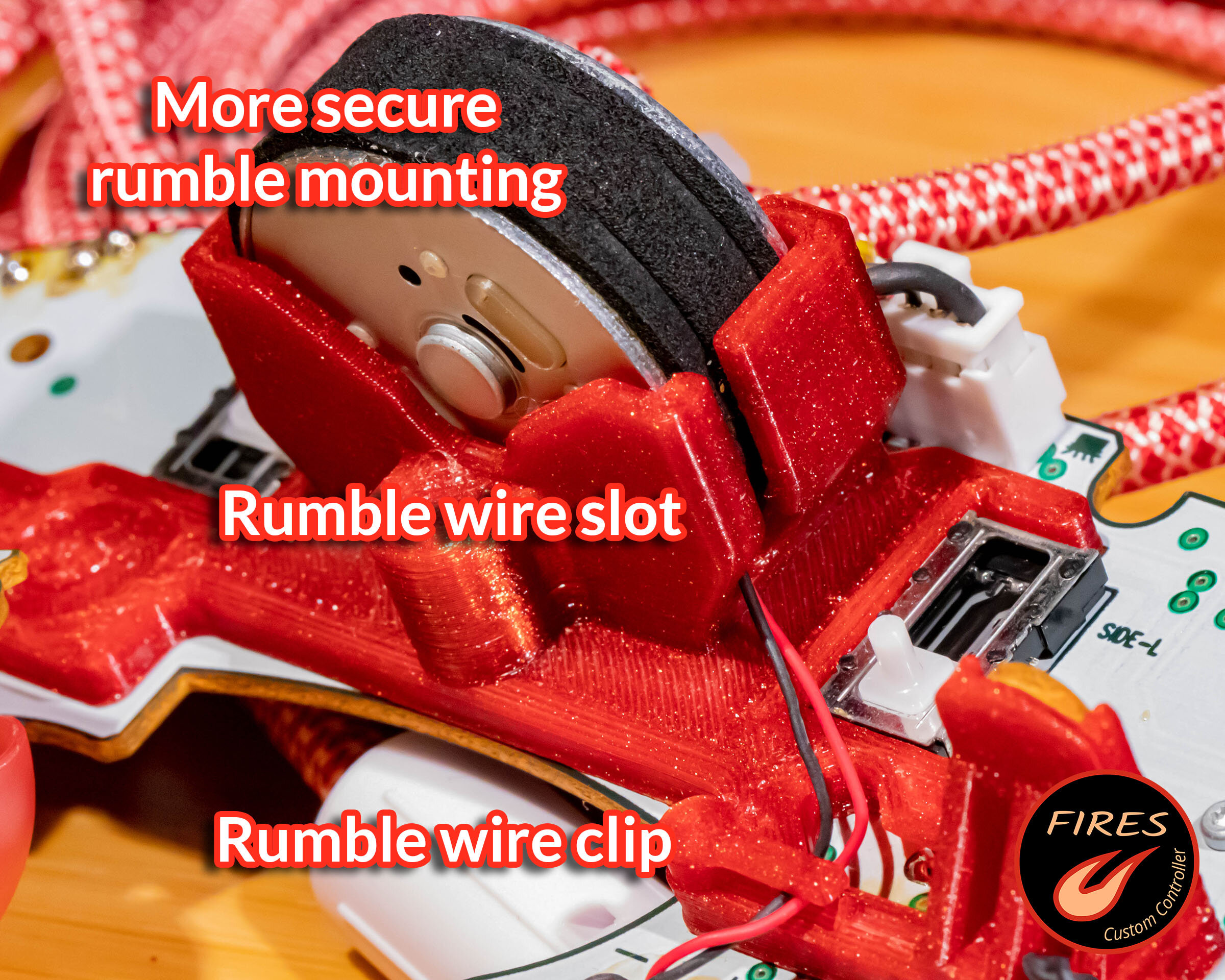
Holds the rumble motor much more securely compared to the OEM design
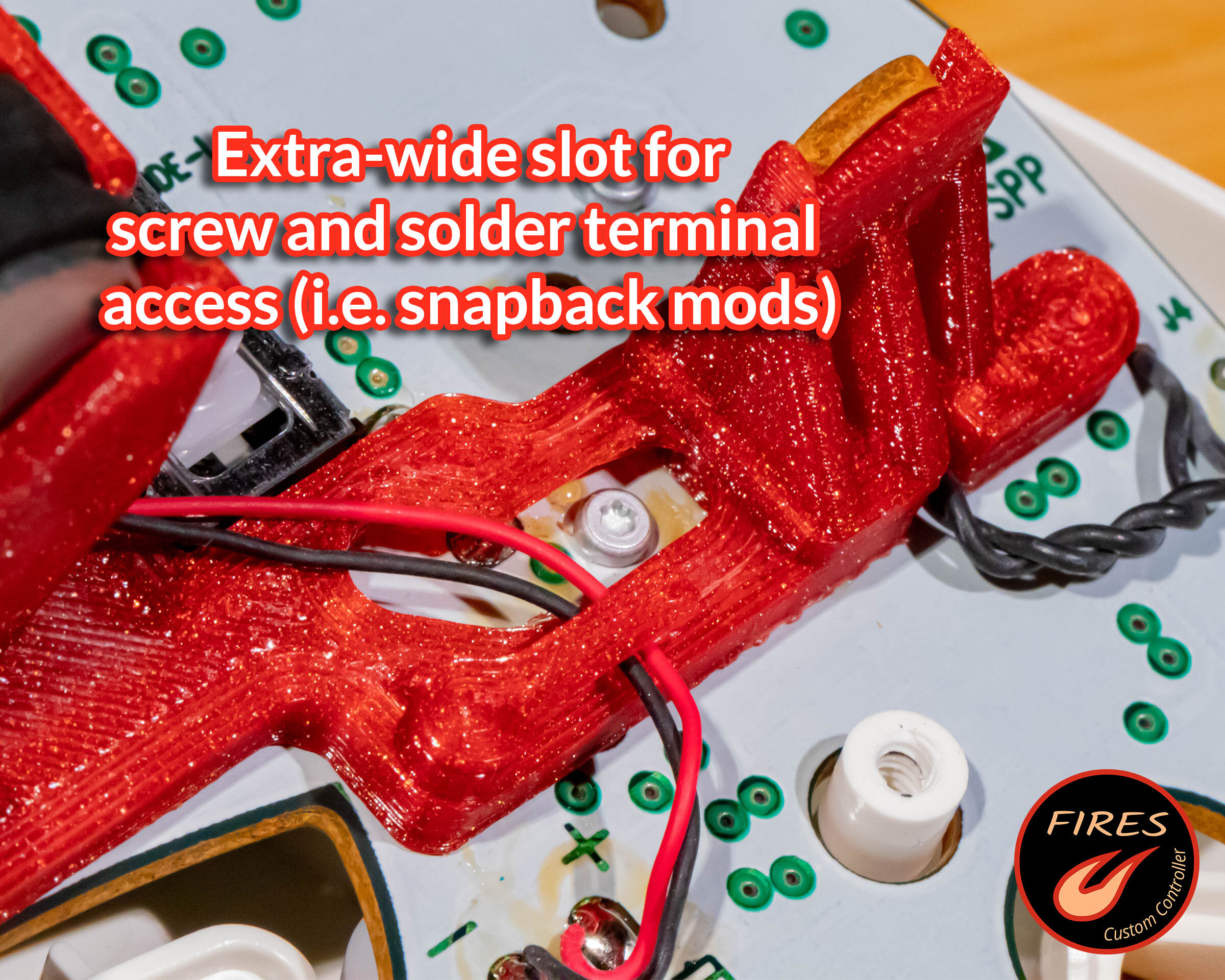
Much more space near the analog stick potentiometer pins for installing snapback mods
Customizable to match any color scheme and enhance the look of your controller, especially with clear shells!
Time:
10 min
Difficulty:
No specialized skills or expertise required.
Type:
Quality-of-Life Mod
Tools Required for Installation:
- ScrewdriversTorx T5 needed to install new screws. Triwing Y2.5 and Phillips #0 for stock controller screws. Torx T8 to open shell if you’ve done the torx screw upgrade
Tools Required to Create Your Own:
- 3D Printer
- Tweezers: For safely holding inserts while installing
- Soldering Iron: For installing heat-set inserts (no soldering)
- Optional: Drill BitM2.2 drill bit recommended. 5/64" will also work
Parts List:
- FIRES Rumble Bracket:
(a) Link to free 3D-printable CAD files
(b) Link to premade brackets (FIRES Etsy Store) - 2x M1.6 Screws: M1.6 x 0.35mm, 4mm length torx
- 2x M1.6 Heat-Set Inserts: M1.6 x 0.35 mm, 3mm length brass inserts
Print Settings:
Recommended 3D Print Settings:
Orientation: Circuit board side facing down
Material: PETG recommended, PLA OK
Layer Height: 0.15mm
Infill: 100%
Support Material: Highly recommended for multiple overhang features: bridges above the left analog stick potentiometer pins, rumble motor wire clip, etc.
Scale: May need minor tweaks to X/Y scaling to achieve a perfect fit depending on printer accuracy
Post-Print Processing
Clean Print:
Use a small needlenose pliers to remove all support material. Flush cutters are very useful for removing stray plastic nubs or strands.
Due to variations between printers and print profiles, it’s a good idea to verify the correct fit of:
Digital trigger boards
Rumble motor
Rumble bracket on circuit board
If any of these fits are wrong, you may need to slightly tweak the 3D model or adjust X/Y scaling.
(Optional) Drill insert holes:
We’ll be using brass heat-set inserts to make a stronger connection. It’s possible to use self-tapping screws, but they will strip much more easily and require some adjustment to the 3D model hole dimensions.
Depending on your 3D printer’s accuracy, you may need to drill out the heat-set insert holes. If so, an M2.2 drill is ideal, but a 5/64” drill will work fine.
Install heatset inserts:
Set your soldering iron to 350F / 175C. Both brass inserts will be installed from the circuit board side of the rumble bracket. A pointed (cone) soldering iron tip is recommended for this step.
Use a tweezers to hold and align a brass insert with one of the drilled holes. Gently press the insert into the hole with the tip of the soldering iron. The insert may not move at first - it can take a few seconds to heat up the brass and surrounding plastic.
Push the insert until the top face sits just below the surface of the plastic. Double check that it has not been installed crooked. Repeat for the other insert.
Trim rumble motor wire clip:
Using a flush cutters, trim off the small post on the right side of the rumble motor wire clip. A snip at the top and bottom of the post will do it.
This clip may or may not exist depending on rumble bracket version.
Installation:
Insert left and right digital trigger circuit boards
Put bracket into place and ensure it sits flush with the board (especially the “clips” at the top of the potentiometers). On some potentiometer versions the bracket may audibly “click” into place.
Install and tighten the two mounting screws at the left and right (screws install from the front of the circuit board). While tightening, it is recommended to pull the bracket towards the “bottom” of the board so the clips are held firmly against the potentiometers.
Install rumble motor and guide the wires through the rumble clip.
Reassemble controller!